DOCUMENT
NO.
REV.NO
PAGE
STANDARD
NAME
SPECIFICATION FOR APPROVAL
00 8/10
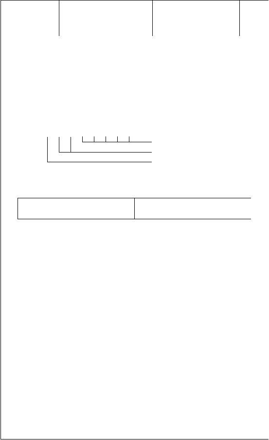
The duty cycle control byte contains a five bit numeric field (bits 4 to 0) that allows
the ‘on’ time for all digits to be modified. Luminance levels are available in 1/32 or
3.1% steps. A value of 31 represents maximum luminance, while a value of 0 places
the output drivers into the “off” state and blanks the display.
For example, a binary value of 24 would force the display’s luminance level to be
77% of maximum luminance, and the full 8-bit byte would be:
1 1 1 1 1 0 0 0
Timing data.
Duty cycle control command.
Control data byte identifier.
4.2 WRITING CHARACTER DATA BYTES
8-BIT DATA BYTE
FUNCTION
0 X Z Z Z Z Z Z
Character Data Byte
NOTES:
1. “X” - don’t care
2. “ZZZZZZ” - 6 bit character address from the character table
Character data bytes are loaded into the data buffer as 8 bit bytes, with the C-bit (bit
7) set to 0. The 64 available data bytes are shown in Figure 6, with their
corresponding ASCII characters.
The display buffer pointer is automatically
incremented before each character data
byte is stored. Decimal points and commas will not cause the buffer pointer to
increment, and are therefore always associated with the character data byte
previously entered. If it is desirable to place characters out of sequence, that is not
from position 1 to 16, then each character data byte must be preceded by the
appropriate positional data through the use of the buffer pointer control byte.
4.3 POWER-ON RESET
Once Vcc has stabilized after power up, a 100us active low pulse must be applied to
the RESET\ input to initialize the module. The following conditions are established
after a RESET\ pulse has been applied.
发布紧急采购,3分钟左右您将得到回复。
相关PDF资料
M0116SY-161MSAR1
MODULE VF CHAR 1X16 5MM
M0120SD-201MDBR1-1
MODULE VF CHAR 1X20 4.9MM
M0121LB-222LHAR2-I1
MODULE VF CHAR 1X21 14.5MM
M0216MD-162MDBR2-J
MODULE VF CHAR 2X16 9.22MM
M0216SD-162SDAR1
MODULE VF CHAR 2X16 4.34MM
M0216SD-162SDAR2-1
MODULE VF CHAR 2X16 5.34MM
M0216SD-162SDAR8
MODULE VF CHAR 2X16 5.34MM
M0220MD-202LDAR2
MODULE VF CHAR 2X20 10.5MM
相关代理商/技术参数
M0116SY-161MSAR1-S2C
功能描述:真空荧光显示器 - VFD VFD Dot Matrix 125.0 x 35.5 x 18.0
RoHS:否 制造商:Noritake 产品:Graphic Display Modules 字符计数 x 行: 模块大小 - 宽x高x厚:230 mm x 78 mm x 15 mm 观察区域 - 宽x高:166.25 mm x 41.45 mm 接口: 电压额定值:5 V 工作温度范围:- 40 C to + 85 C 封装:
M011AA002-01
功能描述:以太网模块 Micro 100 w/RJ45 Jck LEDS TTL pin hdr
RoHS:否 制造商:Lantronix 产品:Device Servers 数据速率:300 bps to 921.6 kbps, 10 Mbps, 100 Mbps 接口类型:Ethernet, Serial 工作电源电压:5 V to 15 V 工作电源电流:133 mA to 400 mA 最大工作温度:+ 70 C
M011U WAF
制造商:Fairchild Semiconductor Corporation 功能描述:
M012
制造商:Kemo Electronic 功能描述:Power Control 110Vac/1200 Va
M012021-00A
制造商:Teac 功能描述:ESCUTHEON;BLACK;FOR CD516E/KIT 制造商:Teac 功能描述:BLACK TRAY FOR CDW516EB02 - Bulk
M012021-02A
制造商:Teac 功能描述:PS/2 TRAY COVER - Bulk
M0120MD-201MDBR2-1
功能描述:真空荧光显示器 - VFD DIM=164.0x34.0x25.5 5 x 8 Dot RoHS:否 制造商:Noritake 产品:Graphic Display Modules 字符计数 x 行: 模块大小 - 宽x高x厚:230 mm x 78 mm x 15 mm 观察区域 - 宽x高:166.25 mm x 41.45 mm 接口: 电压额定值:5 V 工作温度范围:- 40 C to + 85 C 封装:
M0120SD-201MDBR1-1
功能描述:真空荧光显示器 - VFD DIM=150.0x32.0x25.5 5 x 7 Dot RoHS:否 制造商:Noritake 产品:Graphic Display Modules 字符计数 x 行: 模块大小 - 宽x高x厚:230 mm x 78 mm x 15 mm 观察区域 - 宽x高:166.25 mm x 41.45 mm 接口: 电压额定值:5 V 工作温度范围:- 40 C to + 85 C 封装:
